Conform Cells Automatically
This option lets you to take non-intelligent, cell based drawing, and add intelligence to it using the Automatically Cell Conformance Editor to map the cells in the drawing to OpenPlant PID classes.
Accessed when you select the Conform Cells Automatically option from the Conformance Tools gallery.
Once the cells have been mapped and the mapping file saved to the project's schemas directory, the Conform Cells Automatically option will automatically create OpenPlant PID user components from the cells using the mapping file.
Workflow Example:
- Create a dgn drawing, such as shown below with various cell based images. If you click on any one of them and open the Element Information dialog, will display the cell properties:
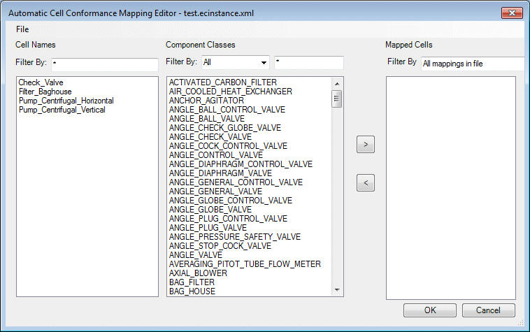
- In the Conformance Taskbar, launch the Automatically Cell Conformance Editor.
- Select File > New and use the Windows file dialog to create a new Mapping file.
- Select the File > Load Cells from Active Drawing option to display the cells in the open drawing in the mapping dialog:
- Select one of the Cell Names from the list.
- Next, select a Component Class from the list to map to the cell.
- Use the arrow icons to add/remove the component class(es) from the Mapped Cell list.
- Once you have mapped all
of the cells, click OK to save the changes and close the dialog.
You will be prompted with a dialog confirming you want to save the changes to the map file.
- Now that the cells are
mapped, select the Conform Cells Automatically option to convert the cells.
A file selection dialog displays prompting you to select a map file to open.
- Select the map file
created above and click Open.
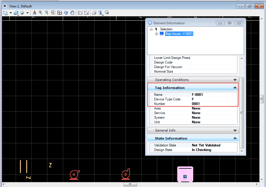
The cell will be converted automatically.
- If you open the Element Info dialog now and click on any of the images, you will notice the image now has a Tag value. Define additional properties as desired.
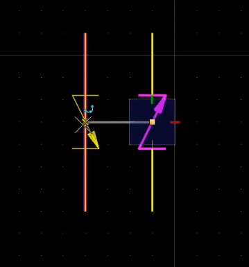
- Inline components, such as the check valves in the drawing will have the ability to rotate to align properly with the flow direction of the line. In the image below, the pipe runs have different flow directions as the check valves indicate. As you drag the new valve over a line, it will rotate to the correct flow direction.